

Custom Powder Metallurgy Parts for High-Performance Industrial Applications
2026-11-21
Most powder metallurgy suppliers can produce a shape. Fewer can hold tight tolerances when the application involves high load, heat, or continuous cycling. XIAYI focuses on the second category: custom powder metallurgy parts built for high-performance industrial applications. In this guide, we look at the design and material decisions that separate parts that merely fit from parts that last.
Alloy Recipes Built Around Specific Stress and Temperature Zones
Alloy development tends to break down once you treat a material as a single answer for every load case. The useful recipes are the ones that start with a narrow window: a temperature band, a stress range, and the time the part has to survive inside that window. From there the adjustments become practical—raising chromium for oxidation resistance at the upper end of the heat range, or shifting nickel content to hold toughness when temperatures swing below freezing.
What makes these recipes work is that they are deliberately unbalanced. A turbine disk formula might sacrifice some room-temperature ductility to keep creep strain in check during long holds at high heat. A cryogenic valve body, by contrast, leans on austenitic structure and controlled nitrogen additions, because the failure mode at -160°C has little to do with creep and everything to do with brittle fracture. The stress and temperature zone defines which property gets priority, and the recipe follows that choice instead of chasing an all-around average.
In practice, small shifts in heat treatment often do more than large chemistry changes. A precipitation-hardening alloy may be aged at a lower temperature to improve stress corrosion resistance in a moderate heat band, while the same base composition aged higher is better suited to short-term strength. The recipe, then, is not just the elements in the melt; it includes the thermal history that locks in the behavior for a particular service window.
Why Net-Shape Consolidation Eliminates Weak Fastener Points
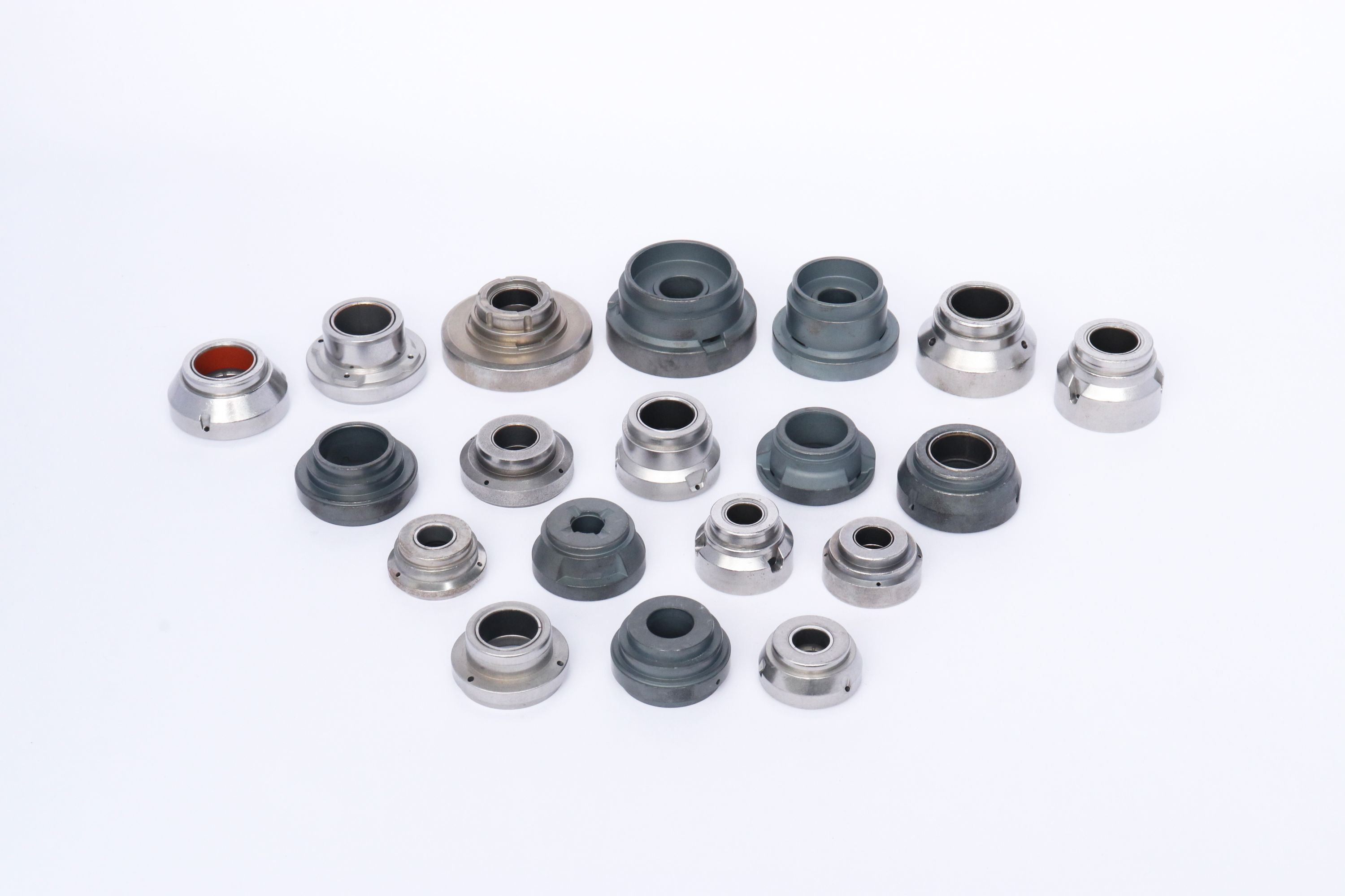
Fastener joints fail in predictable ways. Threads strip, holes elongate, bearing surfaces fret, and clamp load decays as surfaces embed or temperatures change. Net-shape consolidation removes these failure modes by designing the joint out entirely. Instead of relying on a bolt to squeeze two flanges together, the part emerges as one continuous form, so stress no longer has to jump across a clamped interface. That continuity changes how the component behaves under fatigue, impact, and thermal loads.
The improvement goes deeper than simply deleting hardware. A net-shape part can follow a load path that would be impossible to machine or assemble from multiple pieces. Material can be added locally around a boss or rib without creating the sharp transitions that appear around a drilled hole. In powder-based and precision casting processes, the grain structure or density distribution can also be tailored more evenly, which reduces the crack initiation sites associated with cut threads and hole edges.
Field experience tends to favor the consolidated design because there is less to loosen, inspect, or re-torque. Even a properly tightened fastener works by storing elastic energy, and any relaxation in the joint changes the preload and invites movement. Once that movement starts, fretting and fatigue follow quickly. By eliminating the joint, the consolidated part removes the preload dependency altogether and gives a more stable mechanical system over long service intervals.
Pore Architecture as a Design Lever, Not a Flaw
Pores in materials are often treated as defects to be minimized, but when you start thinking of them as a tunable parameter, the entire design space opens up. A controlled pore network can direct fluid flow, trap specific molecules, or even create mechanical anisotropy that solid blocks simply cannot achieve. The key is not to fight porosity but to choreograph it—varying throat sizes, connectivity, and surface chemistry turns a passive void into an active functional component.
Take catalytic supports or battery electrodes: a random sponge-like structure wastes volume and creates dead ends. On the other hand, a pore architecture with graded diameters and asymmetric branching behaves like a customized highway system for ions or reactants. You get lower pressure drop in one direction, faster wetting in another, and selective retention where it matters. This kind of deliberate asymmetry is something you can only unlock by treating pore geometry as a first-class design variable.
The practical payoff shows up in places like filtration membranes, bone scaffolds, and even acoustic dampers. Instead of chasing higher density or lower porosity out of habit, engineers can specify local porosity gradients, throat aspect ratios, and interconnectivity to hit multiple performance targets at once. The flaw narrative disappears once you measure success by how well the void phase does its job—not by how little of it exists.
Post-Sinter Machining and Coatings for Mission-Critical Fit
Sintered parts rarely land at final tolerance straight from the furnace. Thermal distortion, shrinkage variation, and surface porosity all stack up in ways that can push a bore, seat, or locating face outside the window a mission-critical assembly actually needs. Post-sinter machining steps such as honing, ID grinding, face turning, and precision drilling are used selectively to bring only the functional features into control without adding cost to non-critical surfaces.
Coatings enter the picture when the machined surface has to survive more than dimensional inspection. Thin-film treatments like PVD or CVD hard coatings, steam oxide, or resin impregnation can close off interconnected porosity, reduce galling, or provide a controlled coefficient of friction. The choice depends on the failure mode: abrasive wear, micropitting, corrosion, or fretting in a clamped joint. In each case, the coating is treated as part of the fit strategy rather than a cosmetic layer.
The real discipline is sequencing. Machining before coating leaves a clean, dimensionally stable substrate, but coating thickness must be anticipated in the final GD&T stack. Machining after coating risks edge chipping or exposing bare material at sharp transitions. For tight running fits, a short feedback loop between metrology, surface finish data, and coating thickness keeps the final clearance from drifting into either seizure or slop.
Reading Micrographs to Predict Fatigue and Corrosion Behavior
Micrographs often reveal what mechanical testing alone cannot: the early fingerprints of damage before it becomes a full-blown failure. In fatigue analysis, striations left by cyclic loading appear as fine, parallel ridges on fracture surfaces. Measuring their spacing gives a direct read on crack growth per cycle, which then feeds into life prediction models. The trick is knowing where to look. Near the initiation site, striations may be faint or rubbed smooth by contact, while further along the path they sharpen into clear, countable bands. Corrosion adds another layer of complexity. Pitting, intergranular attack, and stress-corrosion cracks each write their own signature into the microstructure, and separating those signals from mechanical fatigue requires more than a casual glance.
A practical approach starts with the sample itself. Replicas and polished cross sections let you track pit depth, width, and undercutting over time without destroying the component. Under the microscope, pits that branch along grain boundaries raise a red flag for stress-corrosion cracking, while broad, shallow pits typically just thin the wall. When fatigue and corrosion act together, the fracture surface often shows a transition: a corroded, mud-cracked zone near the origin, followed by cleaner fatigue striations as the crack outruns the chemical attack. Mapping that transition gives a rough timeline of when corrosion initiated, when cyclic loading took over, and how fast the crack moved thereafter.
Quantifying these features turns micrographs from pretty pictures into predictive tools. Software can now measure striation spacing, pit aspect ratio, and grain-boundary coverage across dozens of images, generating distributions rather than single-point readings. Those distributions matter because corrosion and fatigue damage are inherently local; a single micrograph may flatter or mislead. By combining multiple fields of view with surface roughness data, you can estimate remaining life with reasonable confidence, even when service history is incomplete. The skill lies not in owning a good microscope, but in asking each image a specific question: where did this crack begin, what drove it forward, and how far has it already traveled?
Weight Reduction in Rotating Assemblies Through Density Control
Cutting mass in a rotating assembly is rarely just about the overall weight on a spec sheet. Rotational inertia amplifies every kilogram placed away from the axis, so density control becomes a way to reshape where mass lives, not simply remove it. Swapping a conventional steel hub for a titanium or magnesium alternative lowers the density in the outer sections where centrifugal stress and inertia penalties overlap, often without forcing a redesign of the surrounding hardware.
Powder metallurgy and additive manufacturing extend this idea further by allowing controlled porosity or hollow lattice zones inside parts that would otherwise be machined from solid billet. These internal density gradients pull material away from low-stress cores and keep it in load-bearing walls, so the component stays stiff while its rotating mass drops. The result is a different failure pattern too: lower self-induced centrifugal loads mean thinner sections can survive the same service speeds, compounding the original weight saving.
There is a practical limit, of course. Going too light in a crankshaft, rotor, or drive flange can shift natural frequencies and alter balance sensitivity in ways that show up only during rapid throttle changes or thermal cycling. The better approach treats density not as a single target but as a variable to map across the part, selecting denser material only where stress, wear, or fatigue demands it.
FAQ
The range covers carbon steel, copper steel, nickel steel, low-alloy steel, stainless steel, and soft magnetic alloys. Material choice depends on hardness, wear resistance, corrosion resistance, magnetic behavior, and thermal needs rather than a single best grade.
It offers repeatable dimensions, controlled porosity for self-lubrication, and useful mechanical properties without extensive machining. The process also supports alloy compositions that would be difficult or expensive to cast or forge.
Standard sintering generally holds around ±0.05 mm to ±0.10 mm depending on feature size. Sizing or light CNC work can bring critical dimensions down to about ±0.01 mm. Exact capability depends on the geometry and material.
Most ferrous structural parts land between 6.8 and 7.3 g/cm³, or roughly 87 to 93 percent of wrought density. Heat-treated low-alloy steels can reach tensile strengths above 827 MPa, though elongation is usually lower than wrought equivalents.
Common options include resin impregnation, oil impregnation, steam treating, plating, heat treatment, CNC machining, drilling, and tapping. These are usually applied only to selected features so the base process remains cost-effective.
The process usually becomes attractive around 5,000 to 10,000 pieces per year, but this depends on part size and complexity. Tooling is the main upfront cost, so higher volumes spread that investment more effectively.
Yes. Very sharp internal corners, extremely thin walls, deep cross holes, and severe undercuts are difficult to form and may need secondary machining. A design review early in the project helps avoid ejection problems and tool breakage.
Tool design and fabrication typically take four to eight weeks, followed by sampling and process validation. If special secondary operations or coatings are required, total lead time may extend to ten or twelve weeks.
Conclusion
Custom powder metallurgy parts tend to fall short when the same base powder is expected to handle every load case in a machine. A more useful approach starts with mapping the stress and temperature zones first, then adjusting nickel, molybdenum, copper, or chromium content only where those zones demand it. That localized alloying strategy keeps hardenable areas next to tough, ductile sections without adding a single mechanical fastener. Net-shape consolidation removes threaded joints, press-fit collars, and weld lines that would otherwise act as crack initiation sites under cyclic loading. It also opens room to treat the remaining pore network as a design input: pores can be sized and distributed to hold oil in a bearing journal, interrupt vibration paths, or channel cooling air toward a hot flange instead of being accepted as random porosity.
Once the part leaves the sintering furnace, selective machining is usually limited to mating bores, seal faces, and gear flanks where the as-pressed tolerance is not enough. Applying a coating or surface treatment at that stage protects high-contact areas without trying to plate an entire assembly for corrosion resistance. Before a production lot is released, polished micrographs are read for grain boundary condition, pore morphology, and inclusion distribution, since these features forecast fatigue sensitivity and environmental cracking more reliably than a single bulk density value. For rotating hardware, density is deliberately graded so that low-stress web sections become lighter while the rim or hub retains enough mass and stiffness to carry the operating loads. That reduces inertia and bearing reaction forces without trading away burst margin or dimensional stability.
Contact Us
Contact Person: Leela
Email: [email protected]
Tel/WhatsApp: 8613586885132
Website: https://www.xiayishockparts.com