

Natural Gas Generator Manufacturing: A Complete Guide to Processes, Technologies, and Best Practices
2026-08-04
Natural gas generator manufacturing is a complex blend of precision engineering and sustainable energy solutions. From cutting-edge emission controls to robust engine designs, every step reflects a commitment to reliability. At the heart of this industry, DINGBO POWER has redefined best practices, seamlessly integrating advanced technologies to meet modern power demands. But what truly sets a world-class generator apart? It's not just the machinery—it's the meticulous processes and hidden innovations that few ever see. In this guide, we pull back the curtain on the complete manufacturing journey, revealing the secrets that ensure peak performance and durability.
Raw Material Selection and Metallurgy for Durability
The backbone of any component designed to withstand harsh conditions lies in the initial choice of raw materials. Rather than simply defaulting to familiar grades, a nuanced understanding of how alloying elements interact at the atomic level can dramatically shift long-term performance. Small additions of chromium, molybdenum, or vanadium, for instance, don't just add nominal strength—they alter the way oxides form on surfaces, how carbides distribute within the matrix, and how the metal responds to cyclic stresses over decades. This upfront investment in tailored chemistry pays off when parts resist pitting in marine environments, hold their shape under thermal cycling, or shrug off abrasive wear that would quickly degrade a lesser composition.
Turning a well-chosen ingot into a resilient part demands metallurgical processes that refine microstructure far beyond conventional heat treatment. Controlled cooling rates after forging or precise quenching and tempering schedules push grain boundaries to rearrange in ways that block crack propagation. Techniques like vacuum degassing strip out hydrogen and oxygen before they can create inclusion sites that become fatigue initiation points. Even subtle adjustments—a slight over-aging to coarsen precipitates in aluminum alloys, or a modified austenitizing temperature for tool steels—can mean the difference between a gear that lasts a million cycles and one that fails early from subsurface fracture. These steps aren't just about hitting a hardness number; they craft a material's internal architecture to cope with real-world loads.
Field experience repeatedly shows that shortcuts in material sourcing or heat treatment surface only after years of service. A bridge pinion steel that skips electroslag remelting might operate smoothly for a decade, then snap when a cold snap pushes the ductile-to-brittle transition temperature higher than expected. Conversely, components built with dual-phase microstructures or functionally graded surfaces—where a tough core supports a wear-resistant case—keep machinery running in mines, off-road vehicles, and chemical plants with minimal intervention. The discipline of matching raw stock selection to precise thermal and mechanical processing ultimately defines whether a product becomes a maintenance headache or a benchmark for longevity in its field.
Precision Machining of Engine Components
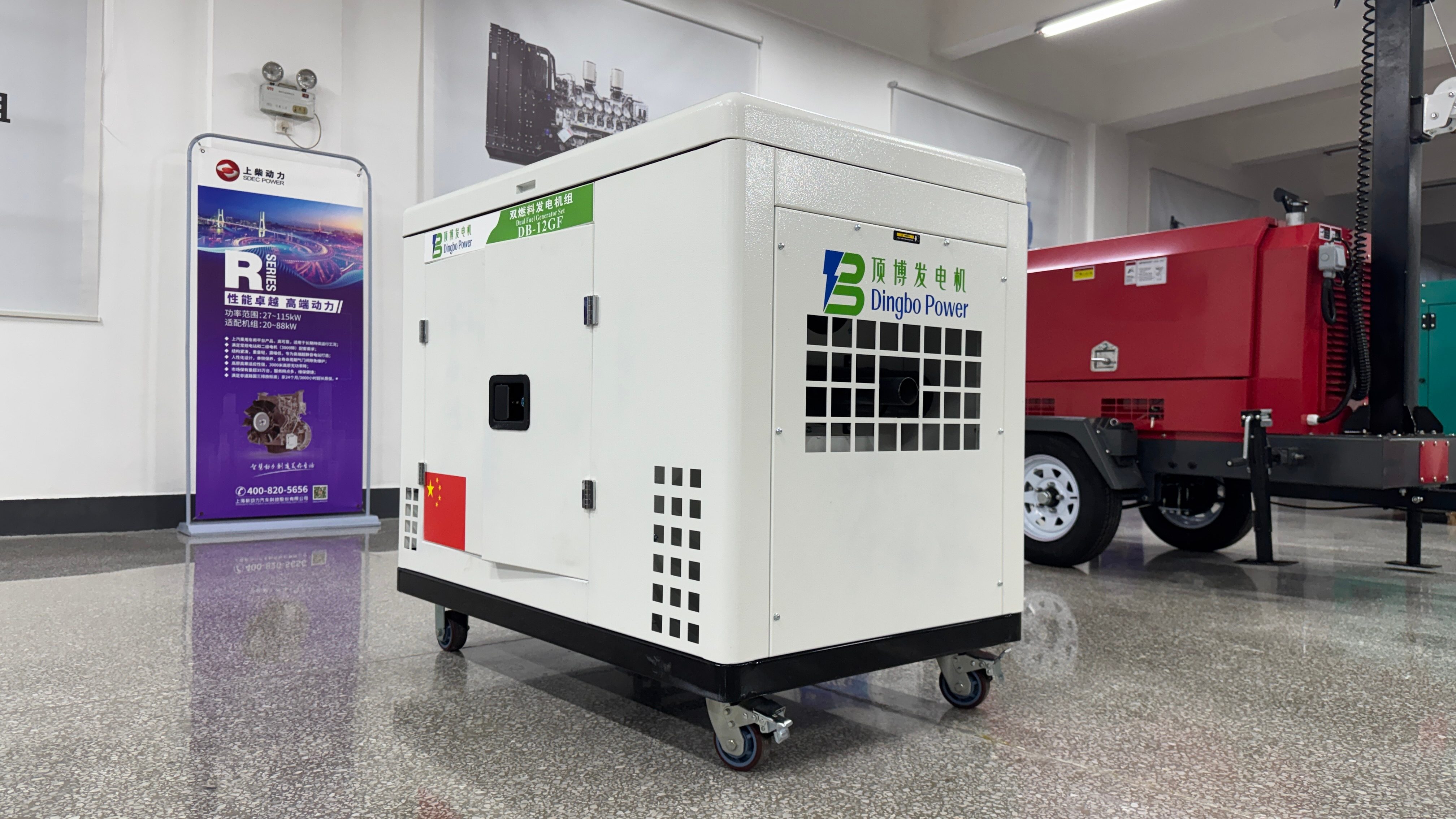
The reliability of an engine hinges on components that fit together with near-perfect precision. Machining processes for parts like pistons, valves, and bearing journals demand tolerances tighter than a human hair, because even microscopic errors can trigger premature wear or oil starvation. Achieving such consistency requires a blend of skilled craftsmanship and rigid process control, where every cut is deliberate and every measurement is verified.
Modern engine designs often incorporate lightweight alloys and heat-resistant superalloys that push the limits of machinability. These materials, prized for their strength-to-weight ratios and thermal stability, quickly degrade cutting tools and warp under excessive heat. To navigate this, shops rely on multi-axis machining centers with adaptive toolpaths, minimum quantity lubrication, and vibration-dampened setups. The goal is not just to shape metal, but to do so without introducing stresses that could distort the part later in its service life.
Beyond dimensional accuracy, surface texture plays a covert role in sealing combustion pressures and retaining lubricant films. Processes like honing and superfinishing create carefully engineered roughness profiles on cylinder walls and cam lobes. The final quality is confirmed through tactile probing and laser scanning, ensuring each component performs as an integral part of the larger system rather than an isolated piece of metal.
Advanced Assembly Line Integration Techniques
Bringing new equipment into an existing assembly line rarely feels like snapping together building blocks. More often, you’re dealing with mismatched communication protocols, physical space constraints, and legacy machinery that wasn’t designed to share data. The real trick is mapping out a middleware layer that translates between old and new without adding latency—sometimes a lightweight OPC UA wrapper does the job, other times you have to get creative with custom signal conditioning. The goal is always to make the integration nearly invisible to the operators on the floor.
Physical integration can be just as thorny. A shiny new robotic cell might have a footprint that disrupts the entire flow of materials if you’re not careful. We’ve found that modeling the line in 3D before any bolts are turned uncovers clashes you’d never spot on a 2D layout. Small adjustments like repositioning a conveyor by a few inches or staggering the placement of vision systems often turn a tight squeeze into a smooth handoff. It’s the kind of detail that prevents hours of downtime later.
Finally, there’s the human element that gets overlooked in too many technical plans. Operators and maintenance crews need to trust the new setup, not fight it. We’ve had success running parallel operations for a week or two—letting people get comfortable while the old line still runs—and then switching over during a planned shutdown. Pairing that with hands-on troubleshooting sessions builds confidence and cuts the usual “new system anxiety” that can quietly drag down output.
Rigorous Testing Protocols for Performance Validation
Ensuring a product truly meets its performance claims demands much more than a simple bench test. It requires structured protocols that mirror real-world stress, uncovering weaknesses that idealized conditions might hide. We start by mapping expected usage patterns: peak load cycles, thermal fluctuations, vibration profiles, and continuous operation timelines. These form the backbone of a custom validation plan, pushing prototypes through extremes that exceed normal limits just enough to reveal margin boundaries without causing unrealistic failures.
Every test run follows a methodical sequence designed to isolate variables. Instead of bundling all stressors into one chaotic trial, we break them into focused phases—accelerated aging, abrupt power cycling, environmental soak tests—each with clear pass/fail criteria. Data streams from multiple sensors are cross-referenced in real time, while automated scripts flag even subtle deviations from expected behavior. A protocol is considered incomplete until it includes not just what to measure, but how to interpret borderline results without bias.
What sets these protocols apart is their built-in adaptability. After initial rounds, findings feed back into the test design itself, refining parameters to chase down anomalies seen in the field. This closed-loop approach means the validation process evolves alongside the product, gradually tightening tolerances and expanding scenario coverage. The final sign-off isn’t a single event but a growing body of evidence that performance holds steady across a landscape of carefully orchestrated challenges.
Emission Control Systems and Compliance Engineering
Modern emission control systems are integral to reducing the environmental impact of internal combustion engines. These systems employ a combination of catalytic converters, particulate filters, and selective catalytic reduction (SCR) technologies to neutralize harmful pollutants such as nitrogen oxides (NOx) and carbon monoxide. Engineering teams must calibrate these components to operate efficiently across varying engine loads and temperatures, ensuring that real-world performance aligns with stringent regulatory standards like Euro 6 and EPA Tier 3. The challenge lies not only in system design but also in anticipating degradation over the vehicle's lifespan, prompting the development of robust onboard diagnostic (OBD) protocols that monitor emission-related malfunctions in real time.
Compliance engineering in this field extends beyond laboratory testing, demanding a deep understanding of global certification procedures and the nuances of on-road verification. Engineers collaborate with regulatory bodies to interpret evolving legal frameworks, conducting extensive durability trials that simulate hundreds of thousands of miles of operation. This process involves sophisticated data logging and analysis, identifying edge cases that might trigger non-compliance, such as cold-start emissions or high-altitude operation. By integrating predictive modeling with physical validation, teams can preemptively adjust control strategies, bridging the gap between static certification cycles and dynamic real-world conditions without compromising drivability or fuel economy.
A critical yet often underestimated aspect is the harmonization of hardware and software during the development cycle. Emission control calibration requires iterative fine-tuning of injection timing, exhaust gas recirculation (EGR) rates, and aftertreatment thermal management. Engineers must balance conflicting demands—minimizing urea consumption in SCR systems while maximizing NOx conversion, or optimizing diesel particulate filter regeneration intervals to prevent ash accumulation yet avoid excessive fuel penalty. This multidisciplinary effort relies on a feedback loop of simulation, dynamometer testing, and fleet trials, where even minor miscalculations can lead to costly recalls or reputational damage. Consequently, state-of-the-art facilities invest heavily in proprietary algorithms and hardware-in-the-loop setups that replicate diverse operating environments with high fidelity.
Enclosure Design and Noise Attenuation Strategies
Designing an effective enclosure starts with a fundamental understanding of how sound energy travels through different materials. Rather than simply surrounding a noisy component with the thickest barrier available, engineers often focus on mass-law principles and critical frequency mismatches. Dense, limp materials like mass-loaded vinyl can be strategically layered to disrupt transmission paths, especially when decoupled from the source using vibration isolators. For airborne noise, even small gaps or seams can undermine an otherwise robust design, so attention to sealing methods—such as interlocking joints or acoustic gaskets—is just as crucial as material selection.
Internal reflections can quickly escalate noise levels within an enclosure, making absorption a key part of the strategy. The placement of absorptive materials is guided by the wavelength of the dominant frequencies: porous foams or fiberglass work best where their thickness approaches a quarter wavelength. In compact designs, resonant absorbers—like perforated panels backed by air cavities—target specific low-frequency hums that thicker liners struggle to address. Sometimes the most effective move isn't adding more absorption but rethinking internal geometry, using sloped or curved surfaces to prevent standing waves from forming in the first place.
Active attenuation measures are increasingly paired with passive designs to handle varying or unpredictable noise profiles. A well-tuned feedback system can inject antiphase signals through speakers mounted inside the enclosure, canceling out narrowband tones that originate from rotating machinery. The challenge lies in capturing the noise accurately with microphones placed in the pressure zone, then processing the signal before the sound field changes. Many modern solutions blend this with adaptive filtering, allowing the enclosure to remain effective even as operating conditions shift. Ultimately, a holistic approach that combines structural isolation, smart absorption layout, and real-time electronic correction often yields better results than relying on any single tactic.
FAQ
The engine block and generator head rely on high-grade cast iron or aluminum alloys, while copper windings and rare-earth magnets are essential for efficient power conversion. Catalytic metals like platinum can also be used in emission control components.
Most facilities run a battery of tests including a full load bank test at varying power factors, insulation resistance checks, and harmonic distortion analysis. Noise levels and vibration signatures are often measured in semi-anechoic chambers.
Absolutely. Standby units typically have lighter-duty cooling systems and simpler controls since they run for short outages. Prime power gensets get heavier flywheels, oversized radiators, and robust fuel delivery systems to handle continuous loads in remote operations.
Pulsed MIG welding is common for the structural steel base to reduce heat distortion and ensure full penetration. Some manufacturers use robotic TIG for stainless steel enclosures to get cleaner seams on visible panels.
Beyond the three-way catalytic converter, many lines now install lean-burn engine calibrations and exhaust gas recirculation kits directly on the production floor. SCR systems are retrofitted to larger units above a certain kW threshold right after the engine dress-out stage.
Digital twin software lets engineers simulate the entire genset before physical assembly, catching layout clashes. On the floor, augmented reality goggles guide technicians through complex wiring harness installations, slashing rework rates.
Proper surface prep before painting is crucial—many shops use a multi-stage wash with iron phosphate coating. Inside the alternator, controlled humidity booths and conformal coatings on circuit boards prevent moisture damage before the unit even leaves the factory.
Conclusion
The manufacturing of natural gas generators begins with meticulous raw material selection and advanced metallurgy, ensuring engine components withstand high thermal and mechanical stresses. High-grade alloys and cast irons are chosen for their durability and corrosion resistance, with metallurgical processes like controlled cooling and surface hardening enhancing part longevity. Precision machining then shapes pistons, cylinder heads, and crankshafts to micron-level tolerances using CNC equipment and specialized cutting tools, which minimizes friction and maximizes combustion efficiency. Once components are ready, an integrated assembly line combines robotic automation with skilled manual oversight to ensure consistent fit and alignment. Advanced assembly techniques, including modular construction and real-time monitoring, streamline the process, reducing errors and accelerating throughput without sacrificing quality.
Following assembly, each generator undergoes rigorous testing protocols—load bank trials, thermal imaging, and vibration analysis—to validate performance and reliability under simulated real-world conditions. Emission control systems are finely calibrated using catalytic converters and exhaust gas recirculation to meet stringent environmental regulations, demonstrating a commitment to compliance engineering. Finally, enclosure design addresses not only weather protection but also noise attenuation, employing composite materials and acoustic foam to dampen operational sound. Strategic airflow management within the canopy further reduces noise while maintaining cooling efficiency. These interconnected practices—from material science to final validation—reflect a holistic approach to manufacturing durable, efficient, and environmentally responsible natural gas generators.
Contact Us
Contact Person: Rita
Email: [email protected]
Tel/WhatsApp: +8613481024441
Website: https://www.dbdieselgenerator.com/