

OEM PTFE Guidewire Design Considerations for High-Performance Medical Devices
2026-10-01
What separates a mediocre PTFE guidewire from one that delivers consistent high-performance in demanding medical procedures? The answer lies in a series of OEM design considerations that are rarely discussed but critically important. INT has built its reputation on mastering these details. Read on to explore the key factors that elevate guidewire performance from ordinary to exceptional.
Why PTFE Coating Thickness Changes Everything in Tight Lesions
In tight lesions, clearance is measured in fractions of a millimeter, so the PTFE coating is not just a surface finish—it becomes a structural variable. A coating that is too thick adds meaningful outer diameter, forcing the device to wedge against the lesion instead of sliding through. Conversely, an overly thin coat may wear off after repeated passes, exposing the bare metal and increasing friction sharply. The right thickness keeps the profile low enough to cross while maintaining a continuous lubricious layer.
Coating thickness also changes how force transfers from the hub to the tip. Each extra micron of PTFE adds a slight stiffness penalty, which is negligible in open vessels but magnified in tortuous, calcified segments. When the device meets resistance, a thick coating can crack or delaminate at the point of maximum bend, creating a rough edge that grabs tissue. A carefully tuned thickness flexes with the underlying shaft, preserving smooth pushability without sacrificing torque response.
Field experience shows that switching from a 5-micron to a 3-micron PTFE layer, for example, can turn a device that hangs up at the lesion into one that crosses with minimal manipulation. This is not because the thinner coating is slipperier in a bench test, but because it leaves more room for the device to find the path of least resistance. In tight lesions, that small difference in coating thickness is often the line between a successful first pass and a prolonged, high-risk procedure.
Designing Guidewire Tips That Balance Flexibility and Pushability
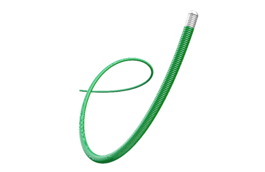
Achieving the right feel in a guidewire tip often comes down to how the distal taper is ground. A gentle, elongated transition spreads bending stress across a larger segment, letting the wire wander through tortuous vessels without buckling. Shorten that same taper and the tip becomes noticeably stiffer, transferring more push from the proximal end but sacrificing some of the delicate navigation needed in tight curves.
Material pairing matters just as much as geometry. A nitinol core with a stainless steel distal segment can deliver a soft, shapeable leading edge that still tracks well, while a full nitinol construction tends to resist kinking but may feel too springy when trying to cross a resistant lesion. The trick is to engineer the flexural stiffness profile along the last few centimeters so it drops off smoothly rather than abruptly.
Coatings and surface treatments also shift this balance. A hydrophilic layer reduces friction, which helps the wire slide forward with less force, effectively improving pushability without adding core stiffness. Yet if the coating extends too far onto the tip, it can mute tactile feedback, making it harder to sense vessel wall contact. Many designs therefore leave the very tip uncoated or apply a thinner layer to preserve that crucial sense of touch.
OEM Controls for Consistent Lubricity Without Additive Drift
OEM controls are the practical backbone for maintaining consistent lubricity across long service intervals, because they directly address the conditions that lead to additive drift. Whether it is a specific base oil viscosity range, an approved additive package, or a defined operating temperature window, these parameters are calibrated to keep friction modifiers, anti-wear agents, and other surface-active chemistries in balance. When the hardware and fluid are treated as a single system, small variations in load, speed, or contamination do not trigger a cascade of additive depletion. Instead, the lubricant film remains stable, and the frictional response stays within the narrow band that equipment designers expect.
The real value of OEM controls shows up when a machine is run outside generic operating assumptions. For example, a high-pressure hydraulic system may tolerate a non-approved fluid for a short time, but the shear forces and localized temperatures can strip out viscosity index improvers or cause polar additives to plate out unevenly. By following the OEM’s specified oil condition monitoring thresholds and drain intervals, operators can catch these shifts before they turn into measurable wear. In practice, this means tracking acid number, particle counts, and elemental analysis—not as isolated metrics, but as a combined signature of additive health. That signature is what separates a lubricant that is merely present from one that is still doing its job.
Another overlooked aspect is how OEM controls minimize the need for top-up additives or aftermarket friction modifiers. Many field failures come not from the original oil, but from “corrective” dosing that pushes the chemistry out of its designed equilibrium. When the OEM specification is treated as a boundary rather than a suggestion, the temptation to compensate for perceived lubricity loss disappears. The result is a cleaner operating history: fewer varnish deposits, more predictable filter life, and a frictional profile that does not wander with every oil change. In this sense, additive drift is not a mystery to be solved after the fact; it is a failure of control that can be prevented by disciplined adherence to the OEM’s original engineering intent.
How Sterilization Cycles Affect PTFE Surface Integrity
The surface of PTFE components rarely remains untouched after repeated sterilization exposure, even when the bulk material looks unchanged. Autoclave steam introduces moisture and thermal expansion that can gradually roughen the outermost fluoropolymer layers, creating shallow fissures and raising the measured surface roughness from a few nanometers to several hundred nanometers over dozens of cycles. This subtle degradation alters the water contact angle, making the surface less uniformly hydrophobic and more prone to localized wetting.
Different sterilization modalities leave characteristic signatures on PTFE. Gamma irradiation tends to break carbon-fluorine bonds and generate free radicals, which can recombine as oxygen-containing groups or cause chain scission near the surface; the result is a brittle, micro-cracked skin that sheds fine particles under flexure. Hydrogen peroxide gas plasma, by contrast, often attacks the surface through oxidative etching, stripping fluorine atoms and leaving a carbon-rich layer with reduced lubricity. Ethylene oxide is generally gentler, but repeated cycles can still drive low-molecular-weight species to the surface and change the coefficient of friction.
The practical consequences show up in sealing interfaces, sliding contacts, and any application where particulate cleanliness matters. A roughened PTFE surface may still hold pressure initially, but the accumulated micro-damage can increase wear debris, allow biofilm attachment in fluid paths, or compromise the non-stick performance that made the material attractive in the first place. Rather than relying on visual inspection, manufacturers often need to track surface energy, roughness profiles, and fluorine-to-carbon ratios after simulated sterilization cycles to catch degradation before it affects device function.
Geometric Tapers That Reduce Distal Stiffness Jumps
Abrupt shifts in shaft stiffness near the distal segment are a common cause of guidewire and catheter tip instability. When a relatively stiff proximal body steps down too suddenly into a soft tip, the resulting stiffness mismatch concentrates bending at the junction. This creates a hinge point that can make the device bounce off lesion caps, lose push transmission, or traumatize the vessel wall. Geometric tapers address this by spreading the stiffness reduction over a defined longitudinal distance, removing the single weak plane that would otherwise dominate bending behavior.
Rather than a simple single diameter reduction, modern tapers use continuously variable or multi-stage profiles to control the moment of inertia along the distal shaft. A linear taper gives a predictable stiffness decay, while parabolic or exponential profiles bias the flexural change toward either the proximal or distal end depending on the intended navigation task. Core grinding techniques can produce these geometries in nitinol or stainless steel cores, often paired with a polymer jacket that is also tapered in wall thickness. The result is a distal segment that flexes progressively, avoiding sharp bends at any one point.
From a handling perspective, this translates into smoother tracking through tortuous anatomy and a more predictable response to torque. The absence of a localized stiffness jump means the tip remains loaded against the vessel wall without buckling or whipping, even when crossing tight stenoses. Clinically, geometric taper design reduces the need for excessive proximal force, which lowers the chance of distal perforation or dissection while preserving tactile feedback for the operator.
Custom Core Materials Beneath the PTFE Jacket
PTFE jacketing often steals the spotlight for its chemical inertness and wide temperature range, but what sits underneath matters just as much. Depending on the operating environment, the core can be anything from high-strand-count bare copper for maximum flexibility to nickel-plated copper that survives prolonged exposure above 200°C without oxidation. Silver-plated copper, with its excellent high-frequency conductivity, frequently shows up in aerospace and RF applications where signal loss must be kept to an absolute minimum.
For mechanically demanding installations, stainless steel or high-tensile alloys can be drawn beneath the same PTFE jacket, trading some conductivity for dramatically improved pull strength and fatigue resistance. Hybrid constructions—such as a copper core wrapped around a steel strength member—allow engineers to fine-tune the balance between current-carrying capacity and physical durability. Because the PTFE extrusion process is compatible with a wide range of metals and alloys, the core selection is rarely a limitation; rather, it becomes the primary lever for matching a cable to a specific thermal, electrical, and mechanical profile.
FAQ
PTFE offers a unique combination of ultra-low coefficient of friction, chemical inertness, and temperature stability. Unlike hydrophilic coatings that can swell or degrade upon prolonged blood contact, PTFE maintains consistent lubricity without hydration, which is critical in tortuous, time-sensitive procedures. Its hydrophobic surface also reduces thrombus adhesion compared to bare metal, though designers must ensure the coating stays intact during aggressive manipulation.
Thicker PTFE layers can fill micro-irregularities on the core wire, resulting in a smoother glide, but they increase the outer diameter and stiffen the distal tip. A common approach is to apply a 5-15 micron coating on the proximal shaft while tapering to 2-5 microns near the tip, using laser ablation or masking during deposition. This preserves trackability while still reducing friction where it matters most.
PTFE's low surface energy makes direct bonding difficult. Without proper pretreatment, the coating can peel under cyclic bending or guide catheter contact. Effective methods include plasma etching to introduce polar functional groups, applying a tie layer of polyimide or etched fluoropolymer, and mechanical roughening of the core wire. Some OEMs use a sintering step after coating to partially melt PTFE and improve mechanical interlocking with micro-roughened surfaces.
PTFE is a strong dielectric, which can be beneficial for isolating electrical signals along the guidewire shaft, reducing noise in EP studies. However, if a conductive distal tip is needed for sensing or ablation, designers must selectively strip or mask the PTFE near the tip. Additionally, static charge can build on the PTFE surface during rapid advancement, so antistatic additives or humidified packaging are sometimes used to prevent discharge that could interfere with sensitive equipment.
Instead of relying solely on ISO 11070 bend testing, leading manufacturers use custom fixtures that simulate tortuous anatomies with repeated 360-degree rotations and 180-degree bends at body temperature. They monitor coating cracks via scanning electron microscopy after set cycle counts. Fatigue limits are correlated with clinical use data to avoid adding unnecessary stiffness. Finite element analysis helps map stress concentrations at PTFE-to-core interfaces, guiding where to adjust coating thickness or core transitions.
PTFE lowers the dynamic coefficient of friction against catheter liners to around 0.04-0.1, but surface texture also matters. Some OEMs incorporate a secondary treatment, such as a thin silicone overcoat or a patterned PTFE surface created by laser texturing, to break fluid meniscus forces. Others blend PTFE with 5-15% PFA to improve clarity and flexibility while accepting a slight increase in friction.
PTFE can withstand continuous temperatures up to 260°C, so autoclaving does not degrade the coating like some hydrophilic polymers. However, repeated autoclave cycles can cause micro-voids from differential expansion between PTFE and the metal core, so OEMs specify a maximum number of cycles. EtO is gentler on PTFE but requires ensuring no residual gas is trapped in the porous interface, which could later expand inside the body.
For CTO crossing, a PTFE-coated guidewire might need a stiffer core and a more abrasion-resistant PTFE grade with higher molecular weight, plus a distal tip with a different coating (e.g., tungsten-loaded polymer). In thrombectomy, rapid device exchanges demand PTFE that slides easily through aspiration catheters, so a slightly thicker, harder PTFE layer on the proximal segment reduces kinking. Custom colorants or radiopaque markers under the PTFE allow differentiation without affecting lubricity.
Conclusion
In high-performance interventional devices, the PTFE jacket is never just a slippery sleeve—it is a load-bearing interface that dictates how a guidewire behaves inside tortuous, calcified anatomy. Coating thickness, for instance, directly modulates the trade-off between lesion entry and lumen conformity: a few microns too thick creates a stiff, crack-prone shell that resists tight bends, while too thin exposes the underlying core to friction and platelet adhesion. Tip design must then reconcile distal flexibility with proximal pushability through carefully graduated transitions, often achieved with ribbon-wound cores and asymmetric grind profiles that shift bending moments without sacrificing column strength. OEM-level control hinges on maintaining lubricity without additive drift, meaning the polymer formulation and curing process must be locked down to prevent silicone or fluorinated additives from blooming unevenly after repeated use.
Sterilization presents another hidden variable: ethylene oxide, gamma, and e-beam can oxidize or cross-link the PTFE surface at different depths, altering hydrophobicity and micro-roughness in ways that standard post-sterilization tests often miss. A robust design therefore includes pre-compensation in the coating cure cycle or a post-sterilization passivation step. Geometric tapers further reduce distal stiffness jumps by staggering the grind lengths and diameters of the core wire beneath the jacket, preventing hinge points that can prolapse or dissect. Finally, the core material itself—whether nitinol, stainless steel, or a composite—must be selected not only for kink resistance but for galvanic compatibility and thermal expansion mismatch with the PTFE layer, since delamination at the jacket-core boundary is a primary failure mode in long-term dwell applications. These considerations, when integrated early in OEM development, produce guidewires that feel predictable in the hand and perform reliably across diverse lesion subsets.
Contact Us
Contact Person: Jeffrey
Email: [email protected]
Tel/WhatsApp: 86-0633-2230056
Website: https://www.sd-intmedical.com