

VS1 Vacuum Circuit Breaker 12kV OEM - A Comprehensive Guide for Industrial Applications
2026-10-07
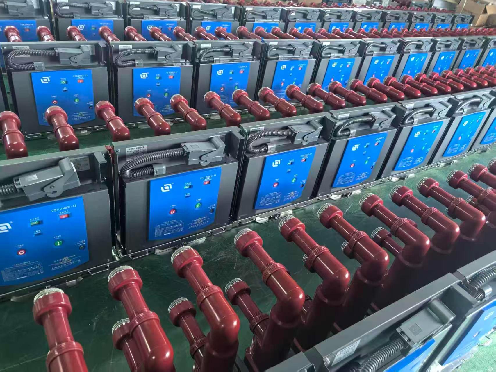
Every industrial facility relies on medium-voltage switchgear to keep operations running, but not all circuit breakers are built the same. The VS1 vacuum circuit breaker rated at 12kV has become a go-to choice for OEMs and plant engineers who need reliable interruption without bulky maintenance. Yet finding a supplier that truly understands your application—not just sells a catalog number—is rare. That's where MOLDVOLT steps in. In this guide, we strip away the hype and walk through what makes the VS1 12kV OEM platform work, where it fits in industrial power distribution, and how to avoid the hidden pitfalls that lead to premature failures.
How the 12kV Rating Shapes Breaker Selection in Industrial Plants
In industrial plants, the 12kV class sits at a practical crossroads where medium-voltage equipment becomes unavoidable—yet still manageable in terms of footprint and maintenance. This rating directly filters the breaker market: you are no longer choosing between molded-case thermal-magnetic units, but among vacuum or SF6 interrupters, each with distinct operating characteristics. The decision often hinges on how the plant handles fault currents, switching frequency, and whether the breaker will live indoors or in a weather-protected switchgear line-up.
A 12kV system typically implies a deliberate compromise between distribution reach and fault energy. Breakers at this voltage must clear faults fast enough to protect downstream transformers and cables, but they also need mechanical endurance for routine switching of large motor feeders or capacitor banks. Many plants standardize on vacuum breakers here because the arc-quenching chamber requires less maintenance than older oil or air-magnetic designs, while SF6 units remain favored where space constraints demand compact, sealed-for-life construction.
Beyond interrupting medium, the 12kV rating shapes selection through short-circuit withstand ratings, creepage distances, and relay coordination. A breaker rated 12kV but with only 25kA interrupting capacity may be inadequate for a bus fed by a large utility transformer, forcing a move to 31.5kA or 40kA designs. Additionally, the voltage class affects enclosure design—metal-clad versus metal-enclosed—and dictates whether the plant can use draw-out breakers for faster isolation or fixed-mounted units to save upfront cost. Choosing well means matching the breaker not just to the nameplate voltage, but to the actual duty cycle and environmental stresses of the facility.
OEM Adjustments That Keep Trip Timing Consistent
Trip timing consistency often hinges on a handful of OEM-level adjustments that rarely make the front page of a spec sheet. The first is throttle response mapping: many bikes ship with a deliberately soft initial tip-in to smooth emissions or reduce driveline shock, but that same delay can make every off-idle launch feel slightly different as temperature and altitude shift. By recalibrating the ECU’s requested torque curve—not just peak numbers, but the first 15% of twist grip travel—a rider gets a predictable, repeatable bite point whether the engine is cold or heat-soaked.
Another overlooked factor is the interplay between traction control intervention and clutch engagement. OEM systems often sample wheel speed at a fixed rate, and when the rear tire momentarily breaks loose on a dusty surface, the cut-and-restore cycle can lag just enough to make two identical launches feel worlds apart. Retuning the slip target and the rate at which ignition timing is pulled back lets the bike settle into a narrower window of wheelspin, so the rider’s perception of “same input, same result” holds up lap after lap.
Finally, chassis geometry stays fixed, but suspension damping and sag do not. Small changes in fork oil height or shock spring preload—adjustments that OEMs leave broad for a wide range of rider weights—can shift weight transfer enough to alter how the rear tire hooks up. Matching those settings to a specific rider’s pace and style removes the variable that creeps in halfway through a session, when a softer rear starts packing down and the launch rhythm goes from metronomic to mushy.
Spotting Contact Wear Before It Causes a Failed Interruption
Most contact wear gives itself away long before a breaker fails to interrupt, but only if someone actually looks for the signs. Rounded edges on arcing contacts, shallow pitting that deepens after repeated operations, and patchy loss of silver or copper plating are common early indicators. Comparing all three phases side by side often reveals one set wearing faster, a pattern that routine maintenance too easily misses.
Resistance checks catch what the eye cannot. A small increase in contact resistance across a closed pole, especially when measured at elevated current, can point to reduced contact force, eroded surface area, or a loose connection starting to build heat. Dynamic resistance measurements go further by showing how the contact surfaces behave during an opening operation, exposing wear that static readings smooth over.
Use the manufacturer's wear markers if they exist, and keep a simple log of measured thickness, wipe distance, or number of operations. When the contact material approaches its minimum dimension, schedule replacement before the next high-fault event. That kind of planned swap is far less disruptive than discovering during a fault that the interrupter no longer has enough contact left to clear it.
Mounting and Busbar Alignment Errors That Shorten Service Life
When equipment is bolted down unevenly or with the wrong torque sequence, the frame distorts just enough to transfer stress into every connected component. A torque wrench used carelessly on one corner can pull a busbar out of plane by fractions of a millimeter, but that's all it takes to concentrate current density at the contact faces. Over time, the local heating loosens the joint further, and the cycle accelerates until the plating burns away or the insulation fails. Most installers never see the damage because it hides inside the enclosure, quietly eroding the design margin that was supposed to carry the load for decades.
Busbar alignment is often treated as a cosmetic issue during assembly, yet even a slight twist or offset forces the bolted interfaces to carry mechanical shear in addition to electrical current. The result is a contact patch that only partially touches, leaving narrow high-resistance pathways that glow under infrared inspection but go unnoticed in routine checks. Repeated thermal expansion and contraction then works the misalignment like a fatigue test, loosening hardware and inviting oxidation into the microscopic gaps. A system that looked straight on the drawings becomes a chain of weak links, each one stealing a little more service life until the next maintenance window reveals pitted surfaces or melted insulation.
The practical fix starts long before the first nut is tightened. Use precision shims and laser alignment tools to verify that all busbar sections sit flat and parallel before applying torque, and follow the manufacturer's tightening sequence exactly instead of working around the room in a circle. After commissioning, periodic infrared scans and torque rechecks catch the early signs of creep and relaxation before they turn into hot spots. Spending an extra hour on alignment during installation routinely adds years to the operating life, while skipping that step guarantees that the weakest mechanical joint will eventually become the most expensive electrical fault.
A Maintenance Schedule Tied to Operating Cycles Rather Than Months
Shifting maintenance away from calendar dates sounds obvious once you see the data. A pump that logs 2,000 hours in three months wears very differently from one that sits idle most of the year, yet a traditional schedule forces both into the same service window. This leads to unnecessary parts replacements on one side and unexpected failures on the other, simply because the interval was picked from a wall calendar instead of actual use.
Operating cycles give a much sharper picture. An engine's oil change point might be tied to hours of rotation, a press brake to stroke counts, or a conveyor to tons moved. Each of these reflects real stress on components rather than the passage of weeks. Once you start tracking the right counter, you stop guessing when a bearing is near its limit and start acting on evidence the machine itself provides.
The practical challenge is that not every asset wears at the same rate per cycle. Heavy loads, cold starts, and dirty environments all accelerate deterioration in ways a simple hour meter misses. That's why many facilities combine cycle-based triggers with condition readings like temperature or vibration trends. The goal isn't to abandon time completely but to use operating data as the primary trigger, with calendar checks reserved for items like sealant shelf life or regulatory inspections that genuinely degrade with time alone.
Upgraded Seals and Coatings for Harsh Factory Environments
In facilities where dust, oil mist, and chemical splashes are constant companions, standard sealing systems simply wear out too fast. The latest generation of seals uses a hybrid fluoropolymer compound that resists swelling from aggressive coolants and maintains flexibility down to -40°F. Unlike older materials that harden over time, these seals keep their lip geometry intact, which means fewer leaks around rotating shafts and junction boxes.
Coatings have moved beyond simple epoxy layers. Modern thermal-sprayed ceramics create a dense, non-porous barrier that shrugs off abrasive particles and acidic washdowns. One field test in a metal stamping plant showed a 70% reduction in seal replacement after switching to these coatings, even with daily high-pressure rinses. The real advantage is in edge retention: corners and threaded fittings that used to chip now hold their edge for months.
Installation practices matter as much as the material itself. A common mistake is reusing old gland plates that have micro-grooves from previous failures. New seal kits include a burnishing tool to smooth mating surfaces, which dramatically extends service life. Combined with periodic inspection of wear indicators molded into the seal body, maintenance teams can plan replacements during scheduled downtime instead of reacting to sudden failures.
FAQ
The sealed vacuum interrupters handle arc quenching in a compact chamber, so there's no oil or gas to maintain. That reduces routine upkeep and lets the breaker sit in dusty or humid switch rooms without losing performance. Industrial plants often choose it because the mechanism is simple enough for local technicians to inspect quickly, and the interrupting capacity covers most feeder and transformer protection duties at this voltage level.
Most OEMs can adjust the chassis dimensions, busbar orientation, and secondary plug arrangements to match a plant's existing switchgear layout. The key is providing accurate panel drawings up front. Some suppliers also modify trip coil ratings or add auxiliary contacts for SCADA integration, which avoids expensive field rewiring later.
Any site with airborne dust, chemical vapors, or wide temperature swings tends to get more value because the vacuum bottle is sealed against contamination. Cement mills, steel plants, and mining substations are typical examples. Since there's no arc chute exposed to the ambient air, the breaker's performance stays stable even when the surrounding room gets dirty.
A practical schedule includes checking the contact wear indicator after heavy fault interruptions, measuring the vacuum interrupter's integrity with a high-voltage tester, and confirming that the closing and opening coil resistances haven't drifted. Lubricate the operating mechanism pivots sparingly and then cycle the breaker a few times to distribute the grease without attracting grit.
Request the full type test report covering short-circuit making and breaking, the mechanical endurance test data, and temperature rise records at rated current. Also ask for dimensional outline drawings, wiring diagrams for the trip and close circuits, and a list of recommended spare parts. A reliable supplier won't hesitate to share these instead of only offering marketing brochures.
The contact material in a vacuum interrupter is chosen to keep current chopping levels low, so the breaker rarely produces the kind of steep voltage spikes that stress motor insulation. If an application involves small inductive loads or dry-type transformers, an RC snubber or surge arrester can be added on the load side. The breaker itself remains a controlled switching device.
Yes, the vacuum interrupter is suited to frequent operations because the arc extinguishes quickly and contact erosion is minimal per switching cycle. However, you should confirm the rated electrical endurance class with the OEM. For capacitor bank switching, specify a breaker version with appropriate inrush current capability and possibly a synchronized closing feature to reduce transient stress.
Conclusion
The 12kV rating on a VS1 vacuum circuit breaker is not just a voltage label; it dictates fault current capacity, insulation coordination, and how the breaker behaves under the switching stresses common in industrial plants. Engineers often overlook that OEM tweaks to the operating mechanism, spring tension, or damping can keep trip timing consistent across batches, which becomes critical when several breakers share a bus. Contact wear is another silent variable. By tracking erosion through contact resistance readings or visual inspection of the arc chutes, maintenance teams can catch a degrading contact before it fails to interrupt a fault. This practice avoids the costly assumption that a breaker is healthy simply because it has not tripped recently.
Field installation errors tend to shorten service life more than any design weakness. Misaligned busbar connections and improper mounting put mechanical stress on the frame and can distort the operating linkage, leading to slow opening or closing. Instead of a calendar-based routine, a schedule tied to actual operating cycles better reflects breaker fatigue, especially in plants with frequent switching. For harsh factory environments, upgraded seals and conformal coatings on internal parts keep dust, moisture, and chemical vapors from compromising insulation. Together these OEM-focused practices turn a stock VS1 breaker into a dependable asset that matches the real demands of industrial switchgear.
Contact Us
Contact Person: Hellen
Email: [email protected]
Tel/WhatsApp: 86-13634205622
Website: https://www.voltcabinet.com